MIL-DTL-62545E
MSEC finds no available extinguishers at a time when a large fire signal is present, it shall sequentially apply an
extinguisher drive signal to each extinguisher (with not more than 2 ms between consecutive drive signals). This is
done on the possibility that extinguishers indicated as unavailable may, in fact, be usable. The MSEC shall not apply
subsequent drive signals until extinguisher availability is again indicated (see figure 1 and 4.6.3).
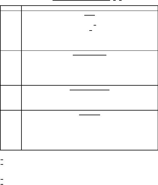
TABLE I. Electrical signal characteristics. 1/ 2/
Symbol
Signal
A
Logic
10 V dc to 30 V dc
Source output impedance ≤ 2,000 Ω 3/
Load input impedance ≥ 20,000 Ω 4/
Quiescent conditions:
1 V dc maximum
Input impedance (source and load) ≥ 20,000 Ω
B
Extinguisher drive
16 V dc to 30 V dc
10 A minimum for load impedance ≤ 1.3 Ω
20 A maximum
Total load impedance: 0.5 to 2.3 Ω
Quiescent condition: See signal C
C
Continuity monitoring
5 mA maximum
Source input and output impedance ≥ 20,000 Ω
Total load impedance: ≤ 2.3 Ω
D
Lamp drive
16 V dc to 30 V dc
Source input impedance ≥ 20,000 Ω
Load impedance ≥ 750 Ω
Quiescent condition:
1 V dc maximum
Source input and output impedance ≥ 20,000 Ω
1/ All outputs shall be capable of withstanding short circuits of indefinite duration.
2/ Whenever a range of values is specified for an input signal or input duration,
the component shall be capable of meeting all requirements at any point within
the specified range.
3/ Less than or equal to (≤).
4/ Greater than or equal to (≥).
4
For Parts Inquires call Parts Hangar, Inc (727) 493-0744
© Copyright 2015 Integrated Publishing, Inc.
A Service Disabled Veteran Owned Small Business